

How to Replace the Pigtail on a Outdoor IP Security Camera

Properly protecting a camera's pigtail from the weather is a necessary step that every installer should take. In the off chance that this wasn't done, you probably lost your outdoor IP camera the first time it rained. In most cases this can be repaired by replacing the pigtail itself. The pinout on the pigtail's RJ45 connector does not follow TIA/EIA-568A or B standards. Therefore, a complete pigtail replacement is necessary. This guide will take you through the steps of replacing the camera pigtail on one of our IP bullet cameras.
How to Prevent Electrical Damage to Your Pigtail
There are a few steps that you can take to make sure that the camera pigtail doesn't get damaged.
- Run the pigtail through the wall. The pigtail runs through the back of the mounting bracket and fishing it through the wall right under the bracket is the ideal way to install a security camera. This technique protects the pigtail from the elements and from potential tampering.
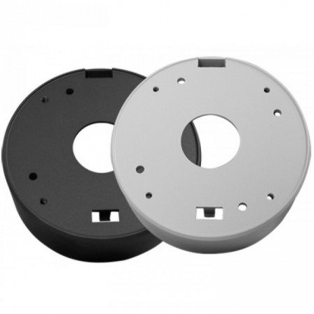
- Use a junction box. If you install the camera using a junction box you can protect a exposed pigtail from the elements. This is an alternative method in situations where running the line through a wall is not a possibility. We carry junction boxes for select model that come with pre-drilled mounting holes, but you can use any camera and drill your own mounting holes as long as the diameter of the junction box matches that of the bracket of your camera.

Note: covering the pigtail connections in electric tape and leaving them exposed to the elements is not weatherproofing.
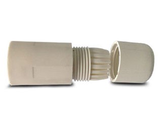
- Cover the RJ-45 connector with a weatherproof boot. You can install a weatherproof RJ45 cable gland around the network connector to protect it from the elements.

- Connect your system to an uninterruptible power supply or UPS.
- UPS devices not only provide power to the system after its lost from the outlet for a limited time, but they also regulate electricity to the devices that are powered by it as well. This way you won't get over voltage or under voltage to the devices.
- Most of them accept RJ-45 as well. Ideally, you would use an NVR with PoE ports on the back to power IP cameras. Run a line from the Router to the UPS, then the UPS to the NVR. Plug the NVR into the UPS as well. Connect all of the cameras to the PoE switch on the back of the NVR. This way your IP camera system is protected from surges. Note that the $15 surge protectors you can buy in just about any department store generally have a protection rating of only 500 joules and don't offer ports for RJ45, etc.
Replacing the pigtail on a bullet IP camera
Note: The housing, position of screws, and mounting orientation may be different on other cameras.
What You'll Need
To replace the camera's pigtail you will the following tools and accessories:
- IP Camera
- Gloves
- Pliers
- Precision Screwdrivers (non-magnetic)
- Camera Specific Allen Wrench
- Electric Tape
- Razor Blade for a Utility Knife
- Specialized Flat Head Screwdriver
- Lens Cloth
- Replacement IP Camera Pigtail
- Philips-head Screwdriver
Disassemble the Bullet IP Camera
It's a good idea to take pictures of the screws in their mounting locations so you have something to reference when you're reassembling the repaired camera later.
To get started on disassembling the camera, begin with the screws on the bracket, and work your way around. Remove the sun shield if there is one. You should have a disassembled mounting bracket at this point. Keep the lens covered still, and remove the locking nut using the specialized screwdriver. Then remove the lens cover. All cameras are not created equally. Yours may differ from the one in the video.
Gain Access to the Pigtail
Once the lens cover is removed, have a look at the board(s) underneath. This camera has 3 printed circuit boards within the housing. We had to remove 8 screws in order to totally remove it from the housing. Yours may be different. Be careful not to bend any pins on connectors between any boards, or scratch the traces with your screwdriver.
Remove the IP Camera's Pigtail
We assume you've located the pigtail's connection point on the CMOS Image Sensor board by this time. Since the pigtail is bad you can cut the line. This will allow you to get the board to a manageable position to remove the 10 pin connector by pulling straight back from the connection point. Doing so will minimize damage to the pins on the board. Pulling the Molex connector out at an angle could bend the pins, or even break them off. Then you'd need a new CMOS Image Sensor board too! At that point, you may as well buy a new camera.
Since you've already removed the locking nut you can pull the pigtail out of the housing. Be sure to set aside the weatherproof piece that is still attached.
Keep track of the order that the pieces came off of the pigtail itself. You'll need to thread the pigtail through them again before inserting it into the housing.
Insert the New Pigtail
With the 10 pin connector attached to the pigtails wiring, there is very little chance of feeding the line through the locking nut without damaging the connector. Therefore, remove the connector. We used a razor blade to lift the levers at each wire on the connector, so we could pull the wire out one by one.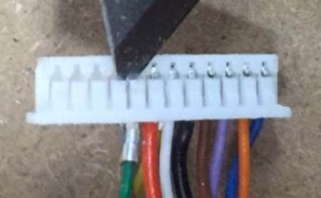 Then tightly wrap the wires with electric tape in order to feed it through everything again, without damaging the wiring.
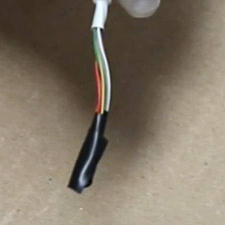
Begin by feeding the line through the pieces in the reverse order they were removed. In our case, it was the IP camera's mounting bracket, followed by locking pieces, followed by the locking nut, followed by the weather strip.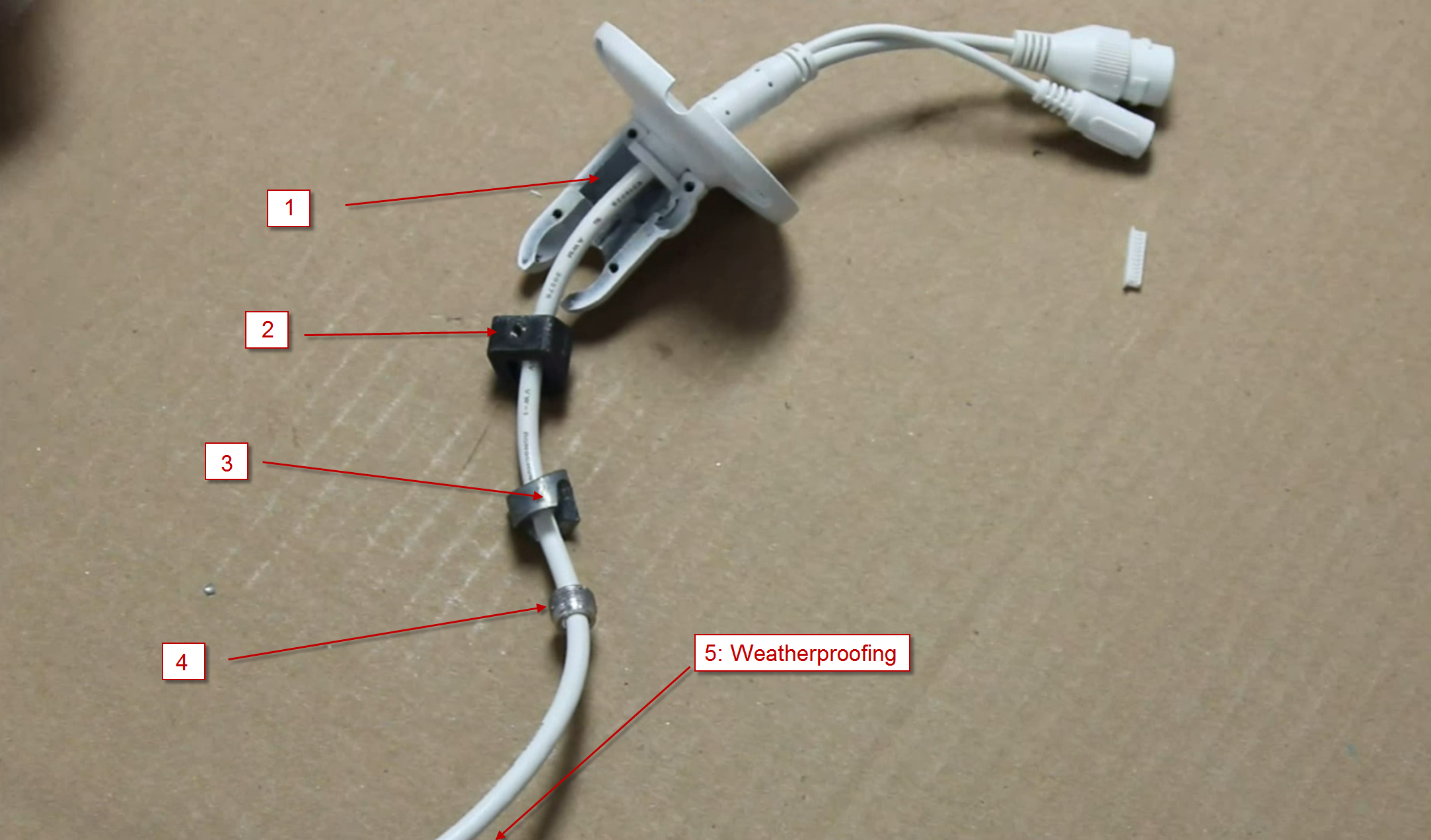 Once they are threaded on the camera pigtail, you can feed the line into the camera housing. Pull the line up enough to work with it, but not so much that you'll leave too much slack within the housing, and cramp the space within that's need for the circuit boards. Then fit the weather stripping into the housing, and tighten down the locking nut on top of it. You want to do this before attaching the connector to the board as the pigtail will move around as you turn the nut. Locking it down after reassembly could cause the wires to come out of the connector, and you'll have to disassemble the camera to reinsert all of the wires that came out. It is important that the pigtails entry point into the housing is a tight fit. If it isn't tight the Ingress Protection rating will mean nothing as this is part of the IP camera's defense against incoming water.
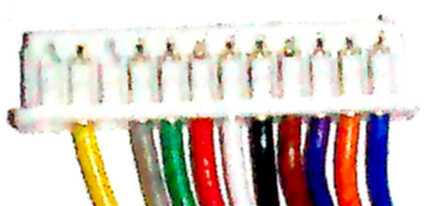
Now that the locking nut is tight, double check to make sure all of the pieces are in the right order on your pigtail, and that nothing is missing. Once you're sure that it's correct you can begin attaching the wires to the Molex connector again. Follow the pinout below or take a look at the wires on the clipped end of the bad pigtail. Make sure you have them in the correct position before moving on. ![]()
Now use a small amount of a non-conductive thread sealer. Pour it onto a disposable surface, and use something to apply it sparingly to the connector. Blow into the top of the connector to remove any fluid that may have gotten into the pin holes. The brand we use normally cures after 24 hours and requires some sort of metal to polymerize. You wouldn't want to clog the pinhole and not have a solid electrical connection with the board. This would essentially insulate the pins from the wires, and not allow communication or power to reach the board.
Mount the Circuit Boards to the Housing
It's time to put everything back together. On this camera, I reassembled the CMOS Image Sensor board before inserting it into the housing. Make sure to line the pins up and push them straight in. Inserting them at an angle could bend the pins. Secure the two boards to each other using screws. You'll have to fish any slack from the pigtail into the housing to make room for the CMOS Image Sensor board. Hopefully, you don't have too much slack. If you do, loosen the locking nut before securing the board to the housing. Slowly remove the pigtail from the housing until the desired amount of slack is present. Then seat the board on the housing and tighten it down.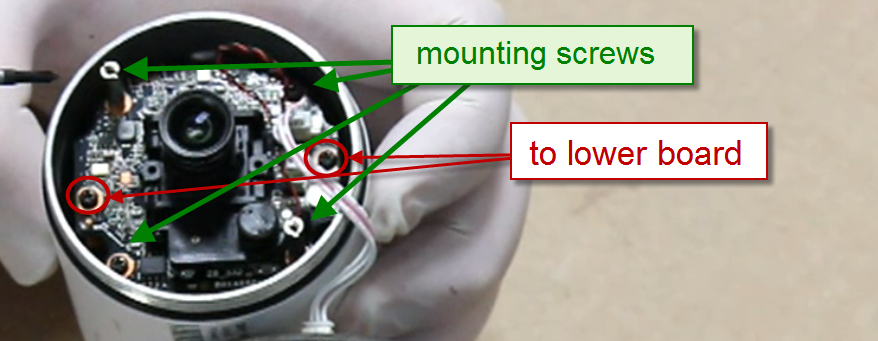 Line the IR board up with the risers on the CMOS Image Sensor board and tighten it down with two screws.
 We're almost done.
Test the IP Camera for Operation
Now is a good time to test the camera to see if it works. It's important to test the camera after securing the boards to the housing because it provides an electrical ground. This helps to protect the board against Electrostatic Discharge or ESD, which can fry the components. Plug the camera into a power source. You can use either a PoE switch or a 12V DC 1 Amp power supply. On this camera, there is a green LED that will illuminate when the board receives power. That's a good sign. Wait for the camera to fully process the startup cycle. Generally, you will hear a click when it's done. Then cup your hands around the housing and over the IR board to block out any light. You can leave a small opening and peer into it.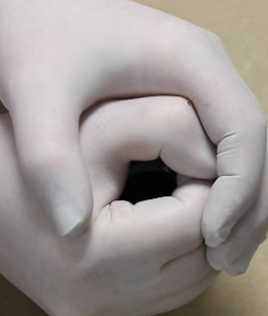 If the camera is working, and its day/night settings haven't been altered, you should see a dim red color coming from the IR LEDs. These IR LEDs have a wavelength of 850nm. Therefore, they are slightly visible within the LED but still produce Infrared light*. If you can't locate your camera on the network but it does get power, check the troubleshooting steps located here. If you have any questions use the discussion box below.
After inspection if you can see the IR glow you can continue to put your camera back together. If you don't it's time to troubleshoot. Unless of course you have a covert camera that uses 950nm wavelength IR LEDs or a camera without night vision. In this case, you should connect to whatever medium you prefer and access it to be sure its functional.
*Infrared Light is defined as a wavelength of 700nm-1mm. Visible light is defined as 400nm-700nm
Finalize the Assembly
At this point, most of the IP bullet camera should be assembled. Before moving forward use a lens cloth to clean the lens on the CMOS Image Sensor board, as well as the inside of the lens cover. Now that it looks pristine you can tighten down the lens cover. Make sure you have it tightly assembled. This is another crucial step to keeping your camera water resistant. When it is tight enough you can begin assembling the mounting bracket.
Seat the internal components of the mounting bracket back in the same orientation they were found.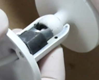 Odds are they will only sit nicely when inserted one way. Then snap the bracket to the housing. Insert the Phillips head screw where it was removed from and begin to feed it through the threads. Don't completely tighten it just yet. Fit the other half on top covering the rest of the bracket, line up the screw holes and begin dropping in the Allen key screws. Tighten them down, then torque them about 1/8 of a turn. Tighten down the Philips head screw and inspect to see if the camera's bracket will move. It shouldn't. Then loosen the screw and test for movement again. This time, it should. Place the sun shield back on top of the housing and tighten it down to the camera. Replace any other removed screws from the housing.
The process is complete. It's a good idea to test the camera again before mounting it to make sure it's still functional, as well as testing the ethernet cable it uses for continuity.
Congratulations! You've repaired your camera!
Troubleshooting Tips
If your pigtail replacement didn't go quite as planned, you can find tips for troubleshooting the repair in our other article How to Replace the Pigtail on a Dome IP Camera.
Compatibility
Most IP cameras use the pinout outlined in this guide. The IP Camera Pigtail should be available from the company you purchased your camera from. It should work for any IP camera from the same vendor. If you're not sure that the pinout will match your camera that you purchased from us, leave a comment in the discussion box below. If you did not purchase the camera from us there is no way we can guarantee compatibility. You'll have to do your own due diligence disassembling the camera to check the pigtail's Molex connector and pinout.