Our 2.4GHz wireless access point radio is a great product to use for long range wireless video transmission, especially in cases where your camera's built-in wireless radio or wireless router are just not strong enough to provide a stable video signal. If you currently have a wireless IP camera and noticed your camera is frequently dropping frames or is getting disconnected, then a wireless access point at either the camera or router, or both, may resolve the issue.
Let's say you don't even have ip cameras, and you would like to send your internet signal from one building on your property to another, then the setup described in this article will help you achieve that task. You will be able to tie in a powerful high gain wireless radio at each end to send a stable and robust WiFi signal. We show in this guide how to setup a Point to Point WiFi connection.
2.4GHz Wireless Access Point
To broadcast the WiFi signal we need a 2.4GHz Access Point for our wireless security camera setup. For solid performance and reliability, we recommend using one of the following Ubiquiti access points or something similar like a Cisco AP.
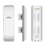
2.4GHz Wireless Outdoor Access Point
- Item NB24
- Strong integrated 11dbi antenna
- Weather Proof construction for outdoor applications
- Also great for indoor industrial applications where there are obstructions
- Up to 1km range (clear line of sight) when used with WiFi cameras with integrated radio
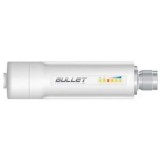
2.4GHz Wireless WiFi Bullet Access Point
- Item IPB24
- Small Size Wireless AP
- Great for indoor applications where space is limited
- Up to 600ft Range (clear line of sight) when used with WiFi cameras with integrated radio
- Requires wireless antenna
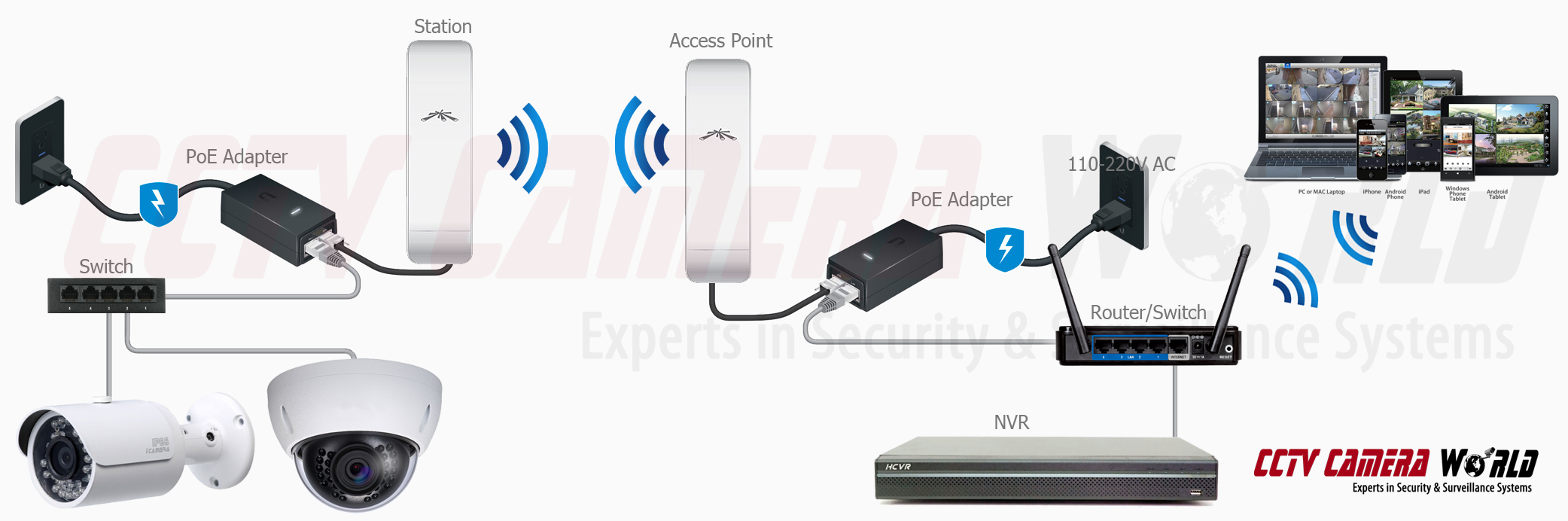
How Wireless Access Points Work
It is important to understand how all this works. We will use two wireless access points to connect to each other to create a point-to-point WiFi connection. Although in our case we are using 2.4GHz models, this setup can be done with 5.8GHz models as well. Each of these units has a WiFi radio and a high gain antenna which makes these units powerful enough for a mile or more of line of sight wireless transmission.
One radio is configured as the Access Point, which sends the WiFi signal that is discoverable as a SSID or available wireless network. The other radio is configured as a Station AP that acts as a receiver station or client on the wireless network. Once the two radios are talking to each other, you have a PTP (Point to Point) wireless link.
Connecting a IP Camera System to Access Points
At the Access Point Side, our setup is geared toward making it possible for the NVR recorder to communicate wirelessly to the cameras located on the Station AP. We connect the Access Point to our router or switch to which the NVR is also connected.
At the Station AP, we can connect one camera directly to the radio, or mutliple cameras to the radio by using a switch in between. We don't recommend using more than 4 cameras per AP, otherwise you will clog your wireless connection with more data than it can handle.
Connecting to multiple cameras using a switch
Directly connecting without a switch
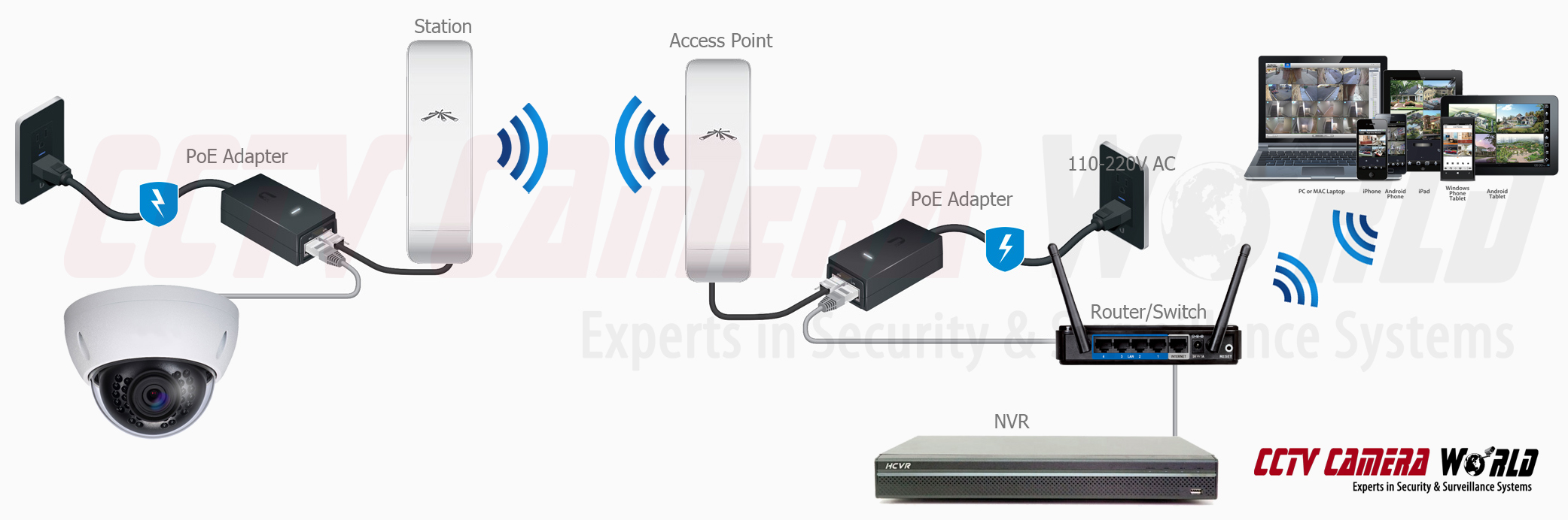
Let's break it down in to layman terms how the signal gets from the camera to the NVR
- The camera sends data over a network cable (through a switch if there are multiple cameras attached) to the Station AP
- The Station AP transfers that data in to a WiFi signal and beams it to the AP at the NVR location
- The AP (Access Point) converts the data received over WiFi in to a wired network signal and sends it to your router
- The router then routes the data to your NVR (also supplies internet to the NVR)
- The NVR records the IP camera streams it is receiving to a hard drive inside, and makes the cameras accessible for viewing from remote users
Using IP cameras makes it easy to make any type of camera wireless and tie it back to the same recorder where other wired or wireless ip cameras are connected. If you use our Tribrid DVR you can even connect other types of cameras that use coax cabling and use wired IP cameras, wireless IP cameras, analog CCTV cameras, and HDCVI HD over coax cameras.
Once you have your cameras streaming back to your security video recorder, you can even do port forwarding and make your camera or NVR accessible for remote viewing from the outside world.
Let's begin with the setup of configuring one IP Security Camera to wire into the Station and send the signal back to the 2.4GHz Wireless Outdoor Access Point.
Step 1: Determine your computer IP address
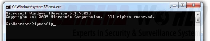
1) Open up the command prompt:
- Click on the Start button on your windows computer
- Type cmd, and press enter
A command prompt like the following will appear. Type ipconfig in the windows command prompt and press Enter.
2) Locate your computer IP address and router IP address in the output from the ipconfig command.
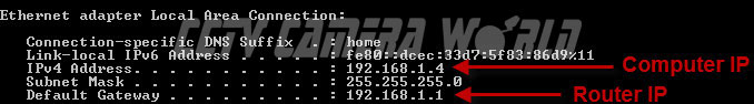
The IP address of the computer you are using will be listed under IPv4 Address, and the Router IP will be listed as the Default Gateway. In our network, the router address is 192.168.1.1 and our computer IP address is 192.168.1.4.
It is important to note that the default IP address for the AP and our ip cameras are as noted below.:
- NVR: 192.168.1.108
- IP Camera: 192.168.1.108
- Wireless Ubiquiti AP: 192.168.1.20
The AP and the Station radios both have the same default IP address before being configured, and will have to have a different IP address to be connected to the network at the same time. For a router with IP address of 192.168.1.1, you only have to change the fourth octet in the default ip address, that is 192.168.1.XXX where XXX is the set of numbers that need to be changed and must be unique for each device on the network. For example, you can configure one camera and two radios as follows:
- NVR: 192.168.1.108
- IP Camera: 192.168.1.107
- Access Point: 192.168.1.95
- Station AP: 192.168.1.96
You may need to change the IP addresses of either one or both AP if there is an IP address conflict or they don't fit your network. You can follow instructions provided in How to view IP Cameras from a web browser on how to change the camera's IP address. You can also find instructions on how to change the IP address of the access point here.
Step 2: Connect the AP to your network
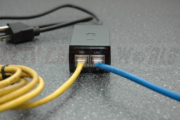
To configure the AP you need to first connect it to your network so you can access it's internal web-based settings page. Each access point comes with a PoE injector. Connect the AP to the power injector using the MAIN (PoE) port, and the power injector to your switch or router using the SECONDARY (LAN) port as pictured below.
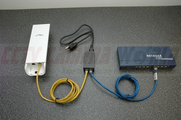
Here is a close-up view of the PoE injector:
Step 3: Login to the AP
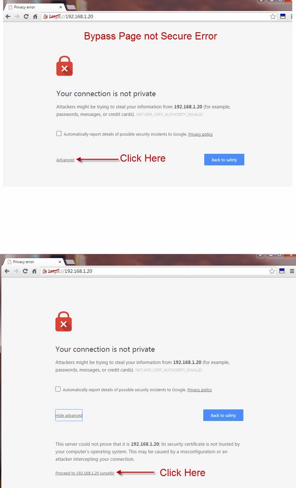
The default IP address of Ubiquiti radios is 192.168.1.20. Be sure you are using a compatible network, and enter this IP address into the address bar of your web browser. If you do not see the login page and get a security error message, follow the instructions provided in the image below. We are using Chrome as the browser in this case.
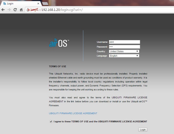
The login page should look like the one below. The default username and password are ubnt and click on the checkbox on the bottom of the page before pressing login.
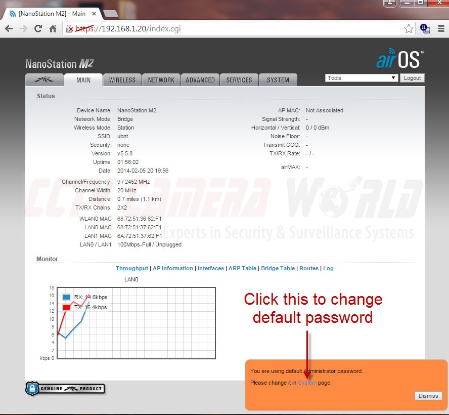
Step 4: Change default password
After you log in for the first time you will be prompted to change the default password. On the bottom right side, there will be an orange colored dialog box. Click on "System" there to navigate to the page to change your password.
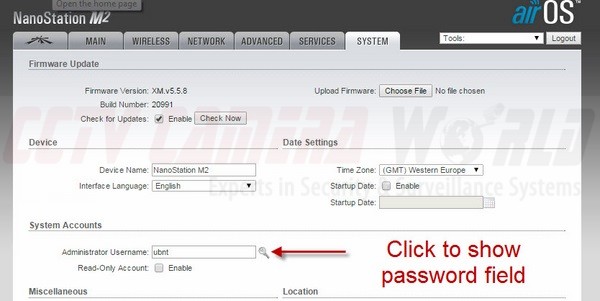
Once you are on the SYSTEM page, change the default password by clicking on the magnifying glass as pictured below to show a drop down section that lets you change the password.
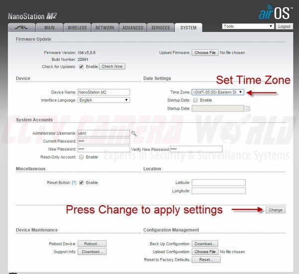
Enter the old password and the new password on this page now. In addition, before saving changes set the Time Zone. When you're done click on the CHANGE button to save your changes.
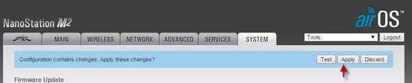
Once you click the CHANGE button look for a blue bar to appear on the top of the screen. Be sure to hit APPLY to save the changes.
You have now successfully done the following:
- Set a custom password and secured your Ubiquiti access point
- Set the correct Time Zone on the device
Step 5: Configure the AP to Access Point Mode
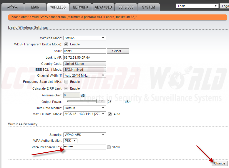
To properly configure two wireless access points to communicate to each other, you have to configure one as an Access Point and the other as a Client Radio. First we will set the Access Point which will transmit the WiFi signal. a) Click on the WIRELESS tab located on the top of the admin page to navigate to the page that allows you to configure radio settings. Take a look at the image below to see how we have configured the radio. Make sure the Channel Width is set to 40 MHz.
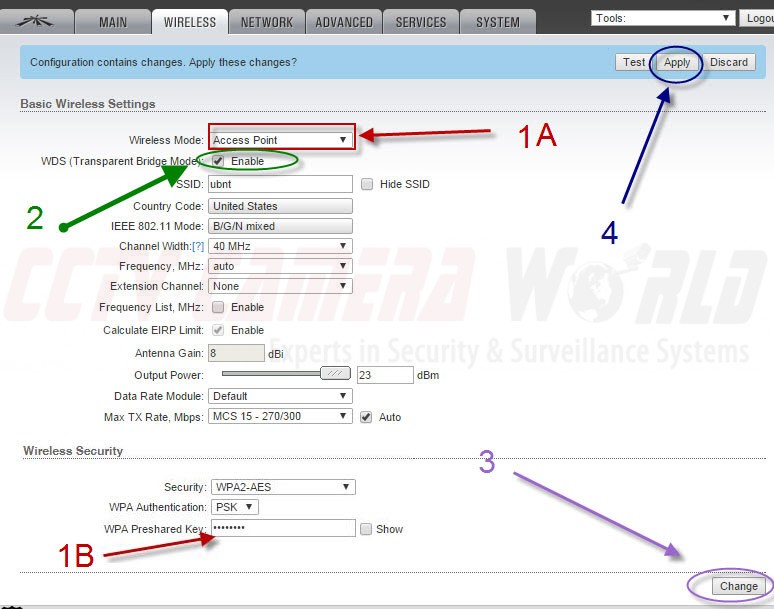
Ubiquiti Wireless Access Point Configuration Settings for radio set as PTP Access Point, with WiFi security enabled.
Here are how the settings must be configured for use on the AP:
- Wireless Mode - Select Access Point
- WDS - Mark the check box labeled Enable
- SSID - This is the name of the WiFi radio you will see under network connections on your laptop
- Country Code - Choose the appropriate country you are located in
- IEEE 802.11 Mode - Select B/G/N mixed for the best compatibility
- Channel Width - Select 40mhz
- Frequency - Set auto. If you have many other WiFi AP in the area, then you can select a channel to minimize interference
- Extension Channel - Select None
- Frequency List - leave this unchecked as we are not selecting specific transmission frequencies
- Calculate EIRP Limit - leave as is (checked)
- Antenna Gain - depending on the strength of the antenna on your AP, it can vary
- Output Power - Put it as max
- Data Rate Module - leave as Default
- Max TX Rate, Mbps - unless you have more than 6 radios in close proximity you can leave this at its default settings as picture below
- Security - Select the type of encryption you would like for the WiFi signal emitted by this AP. Set it as WPA2-AES as it is a very secure encryption
- WPA Authentication - Select PSK
- WPA Preshared Key - assign a WiFi password that you would like to set
- MAC ACL - Leave unchecked
Once you have selected all the settings, click CHANGE on the bottom right, and then look for the blue bar on the top to appear and click APPLY. Otherwise, your settings will not be saved.
Step 6: Turn on MIMO Signal Transmission on Ubiquiti Radios
As of May 2016, almost all of the wireless AP in the supply chain for new products are MIMO enabled. Which means you can only access them with another MIMO enabled access point or laptop. Since you are going to be using another identical AP to receive the signal, then, of course, you want to leave it on. Since we haven't defaulted the device first, let's check to make sure it's on.
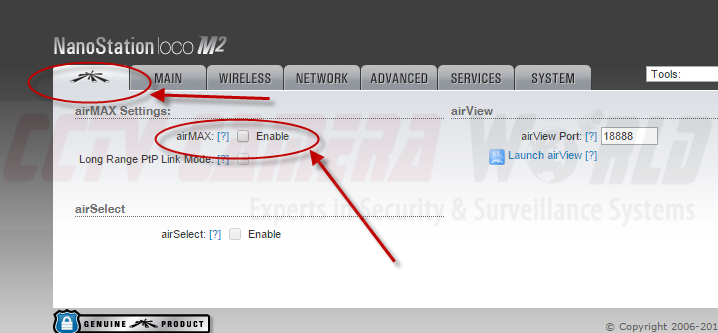
Here is how you turn MIMO on with Ubiquiti access points:
a) Click on the tab containing the Ubiquiti logo. This is the airMax section
b) Make sure the box next to Enable on airMAX is checked
c) Click Change at the bottom right corner of the window
d) Then hit apply at the top of the page
Now the AP is configured to be used as the WiFi signal for another MIMO device only. Let's proceed to configure the IP address.
Step 7: Configure the Radio's IP Address to Avoid IP Conflicts
Given that we have multiple radios that are by default on the same IP address, we have to change the ip address before connecting the next device or there will be a conflict trying to access on the default IP.
Make sure to change the last octet* on the IP address to an open address on your network that is either:
- Later reserved on your network pointing to the device's MAC Address
- Outside of the DHCP range to avoid IP conflicts on the network
- * Octets are separated by a decimal point. The fourth and last octet in the 192.168.1.20 address is the number 20.
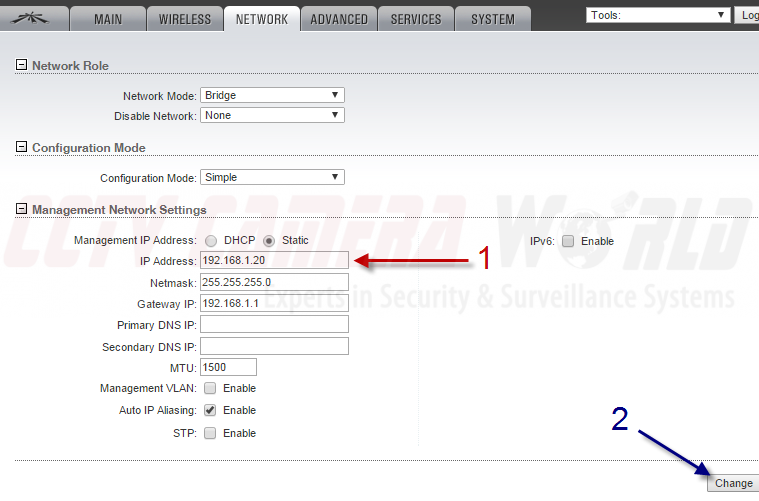
Once you've changed its address click on CHANGE, and if a blue bar appears on the top, click APPLY. We set our AP's ip address to 192.168.1.95 (not shown). The AP will reboot, and your browser should be redirected to the new address of the radio. If it isn't manually enter the new IP address in your browser. Configuration of this AP is complete.
Leave it plugged in and attached to the network at its location for now.
Step 8: Pairing the Station Radio to the AP using MIMO
While the AP is still attached to the network and powered, let's configure the second radio as a Station. Follow steps 2-4 on to access the station and change the password, and set the correct time and time zone.
Now that the station is pulled up and the password is changed click on the WIRELESS tab at the top of the page.
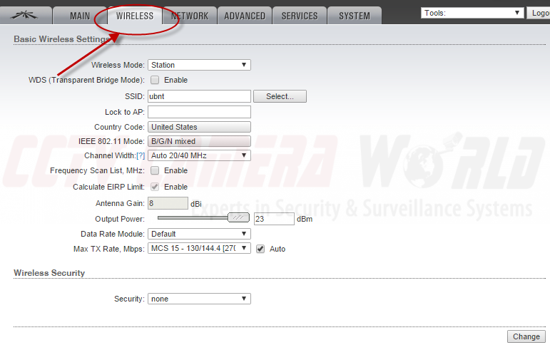
- Wireless Mode should be set to Station
- WDS - if you don't enable it, and the AP has it enabled, it will automatically configure itself as enabled
- Country Code should match your country
- IEEE 802.11 Mode should be mixed b/g/n
- Frequency Scan left unchecked
- Calculate EIRP Limit should be left alone
- Set your antenna gain to its maxim value
- Leave data rate and tx rate at their default values
With all of these settings configured as described above, press the SELECT button located on the right of the text area for SSID.
You will be brought to a menu like the one below. Select your unique SSID from the list given. Click on the radio button to the left of your SSID, then click LOCK TO AP.
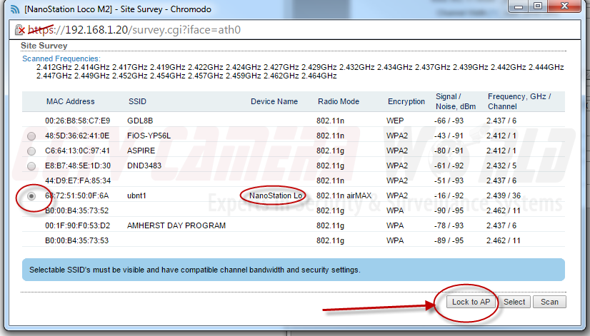
This station radio is now almost paired to work with that specific AP. The SSID and MAC address of the AP will be populated into the form as shown below.
Now select the security encryption type, authentication type, and type the WiFi password you created for the WiFi signal on the AP in Step 5. When you're finished and your Wireless page looks like the above, click on CHANGE then APPLY at the top if it appears.
Once you've finished that you'll need to change the IP address on this Station AP too. Follow step 7 for changing the IP address. We set ours to 192.168.1.96.
The AP and Station are now paired to each other. We suggest testing them for connectivity. There is a signal meter located on the back. When correctly paired and within signal distance you will see something like the following:
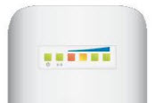
Signal meter located on back of access point provides indication of whether 2 radios are correctly paired.
Both wireless radios are now ready to deploy as discussed above. The AP should go at the location of the NVR, and Station should be connected to the cameras. If you are using one camera, you can use it at the default IP address of 192.168.1.108. If you are using a NVR or more cameras, be sure to change the ip address on them so they don't conflict with their default ip of 192.168.1.108. You can find out how by giving the following guides a read;
If you have questions, feel free to drop a note in the comments section below.