

Configuring IP Cameras on a Network

Connecting IP cameras to an existing network is a tricky task for first timers. You'll have to understand a few principles to really be efficient at setting up your new IP camera system.
What Computer You Should Use During Install
Only use a desktop or laptop computer that has an integrated NIC (aka network port) and administrative rights for the operating system. Using a machine locked down by an IT Admin could cause unforeseen issues attempting to complete the project. Using a tablet with a USB attached NIC is not going to work either. The NIC must be built into your system and be recognized by the BIOS. Antivirus and Firewalls can block communications. Disable them temporarily if you have difficulty. You can use a Mac or a PC. Linux is not supported for this operation. Macbook Air and other laptops without an integrated wired NIC should not be used.
![[+] Click Image to Enlarge](https://cdn01.capitolcam.net/cms/wp-content/uploads/What-nic-type-to-use.png)
[+] Click Image to Enlarge
Network Cable, Transmission Speeds, and Throughput
There are different ratings for different cable types, giving different speeds. Cat5e supports less bandwidth than a Cat6 cable.
Category 5e - 1 Gbit/s Ethernet over twisted pair at 1 Gbit/s (125 MB/s)
Category 6 - 10Gbit/s Ethernet over twisted pair at 10 Gbit/s (1250 MB/s)
While a Cat5e line might be enough for a couple 1080p cameras, using it as a backbone is not advised.
Consider a highway. It is comprised of multiple lanes, allowing vehicles to travel from one location to another. How effective the highway is at its job depends on a ton of factors, but for this analogy, it can be broken down to the number of lanes and the number of vehicles attempting to travel in those lanes at a given time for a set distance.
Network cabling is not much different in a broad scenario. We can compare a data packet to a vehicle, and the bandwidth of the cable to the number of lanes on the highway. However, the vehicles may take up more than one lane at a time due to their size. While you may have a 6 lane highway that can have six vehicles carrying a 1080p signal, the 4mp signals will take up two lanes and the 4K signals will take up 4 lanes. Needless to say, using a cable with a maximum rating of 125MB/s to carry the video to other network devices while you have 16+ cameras is not going to bode well for your transmission speeds. Don't cut corners on your install, make sure you run a good backbone.
Selecting the Correct Network Port
Plugging cables into ports on a PoE network switch arbitrarily will not yield the results you were looking for unless you happened to get lucky and wire things properly. On some of our NVRs and PoE switches, there are a bunch of ports. Let's go over them quickly:
![[+] Click Image to Enlarge](https://cdn01.capitolcam.net/cms/wp-content/uploads/poe-nic-ports.png)
[+] Click Image to Enlarge
PoE Switch 10/100/1000 Uplink Port - Max data transfer rate 1000Mbps, connects the switch to the network, used for the switches backbone
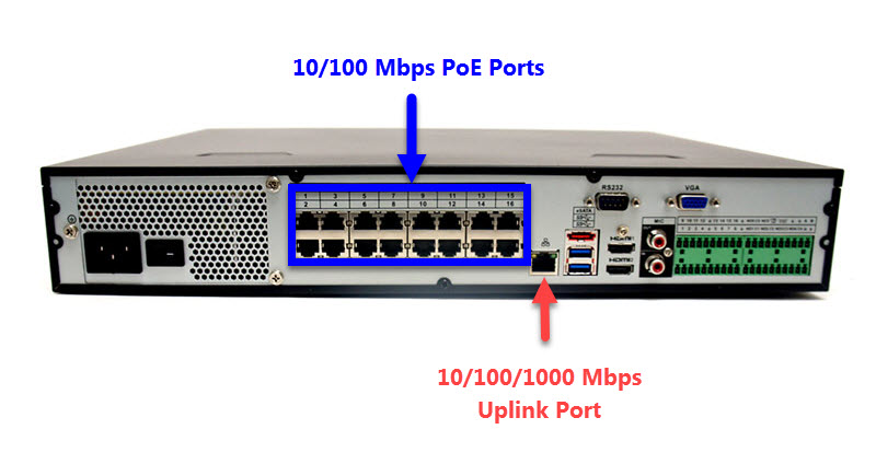
NVR 10/100 PoE Port - Max data transfer rate 100Mbps, only connects cameras, powers cameras, keeps network cameras on a closed system
NVR 10/100/1000 Up/Downlink Port - Max data transfer rate 1000Mbps, separate from PoE ports, some models have two uplink ports. These ports are used to connect the NVR how the unit is reached over the network
Understanding the Scope of IPv4 Dot-Decimal Notation
IPv4 addresses are given in dot-decimal notation. Each value is separated by the dot operator and is one byte in size. One byte is 8 bits. It takes 8 bits to make up an octet. IPv4 addresses are comprised of four octets. We really don't need to get into converting decimal to binary, just understand that in most scenarios the only octet that should differ from one device to another on a LAN is the fourth octet, and the values must be unique and between 1-254.
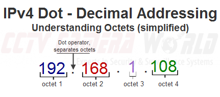
Figure 1-1
Understanding IP Address Conflicts in a Network
Each IP address on a LAN must be unique. If two or more devices on the same network have the same address, each device with that address will turn off their NIC and stop communications on that network until the conflict is resolved. This is usually remedied by removing all but one of the devices with that address, changing the addresses, then reconnecting them to the network.
Why not to use DHCP based IP addresses with your surveillance system
In most computer networks, dynamic internal IP addressing done by a DHCP server on your router will be fine, but not with a network camera system. With IP cameras we don't ever want their address to change, so we must configure a static IP address for each camera connected to the network. If we know the address, we can look for it on the network and attach it to an NVR with a rule. This rule contains the IP address, data port, and login credentials. We can also reach the individual cameras at their IP address using a web browser such as Firefox. If the cameras were to be managed by DHCP:
- We could not keep a list of their IP address as it would change everytime the camera is restarted or the router is rebooted
- The cameras would unsync from the NVR they were connected to because their ip address changed
- We would not be able to configure permanent rules to open ports to specific cameras in order to allow requests for information from an external client
Configuring an Address Scheme for your Subnetwork
Ideally, we don't want to go back and change the addressing scheme for the entire network just to get the data traveling correctly. Instead, you should analyze the network itself, and set the surveillance equipment to addresses that match your existing network. If your network has a default gateway address with anything other than 192.168.1.1 you will not only need to change the fourth octet of each device, but also the first three. If your network is managed by an IT department or some sort of managed services let them handle the addressing. Otherwise, each device on your home or small office network should have the same subnet mask, and the first three octets of the IPv4 address should be the same throughout all of the devices.
If your networks scheme is 10.1.1.(x), and you add the NVR and cameras you received from CCTV Camera World to your network without any configuration, you will not be able to reach the devices via a computer or phone. Any network attached IP cameras will be subject to IP conflict as well as the NVR. You must set their addresses to match your network by attaching and configuring one device at a time.
Network Infrastructure Design with IP Cameras
When you're putting surveillance cameras on your network you really should put some thought into how your network is designed:
- What cabling will you be using , and for what runs and their lengths
- What specific address devices on your network will have
- How the network will be structured physically to reduce collisions and keep data flowing
Essentially we want to try to keep traffic separated. We don't want to interrupt the camera's signal as this is what's being recorded. We also want to be able to use other devices for network traffic. Instead of pushing a backbone to its limit, we'll push traffic through different channels for different devices. Branching devices off in trees to keep the organization of the network is ideal. It helps tremendously during troubleshooting and allows for more bandwidth to the varying devices. Let's take a look at a few different network diagrams.
Below in figure 2-1 we see a Tribrid DVR Network Diagram. Tribrid DVRs do not have integrated PoE ports as they need the space for BNC ports to be backward compatible with Analog and HDCVI. The IP cameras will need to be connected to the network with their own unique address that follows the networks scheme. Wiring the PoE switch improperly, or attaching computers to the same switch you are using to send large amounts of data to a recording device is asking for trouble. Make sure that the uplink port goes back to the network using a cable suited for the amount of bandwidth you will require. Let's take a look at a few different network diagrams.
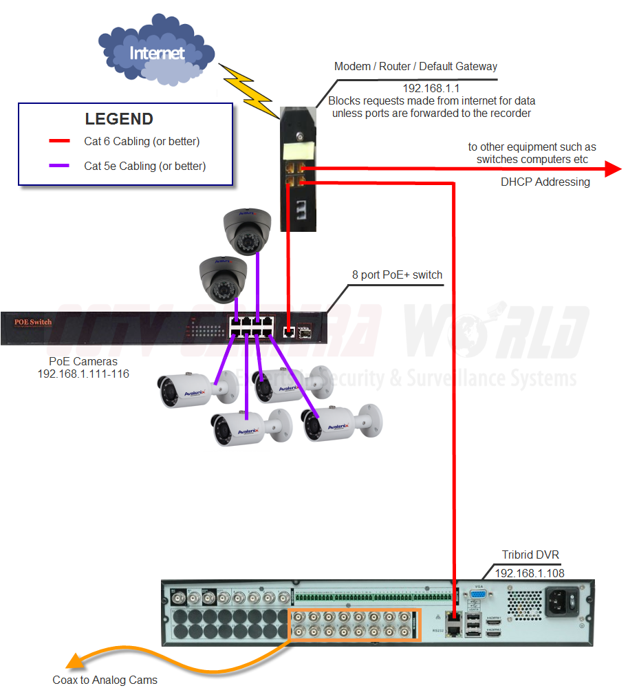
Figure 2-1 Tribrid DVR Network Diagram
[+] Click Image to Enlarge
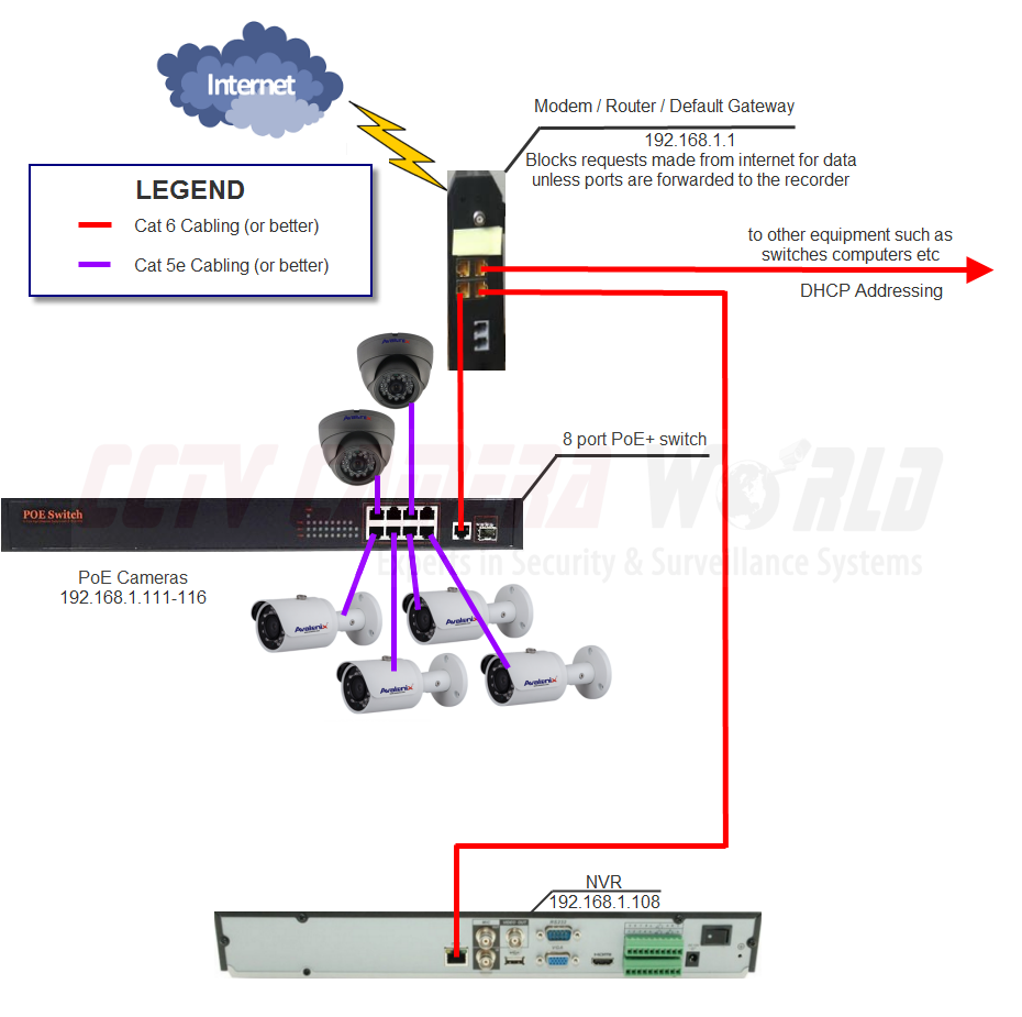
Figure 2-2 NVR
[+] Click Image to Enlarge
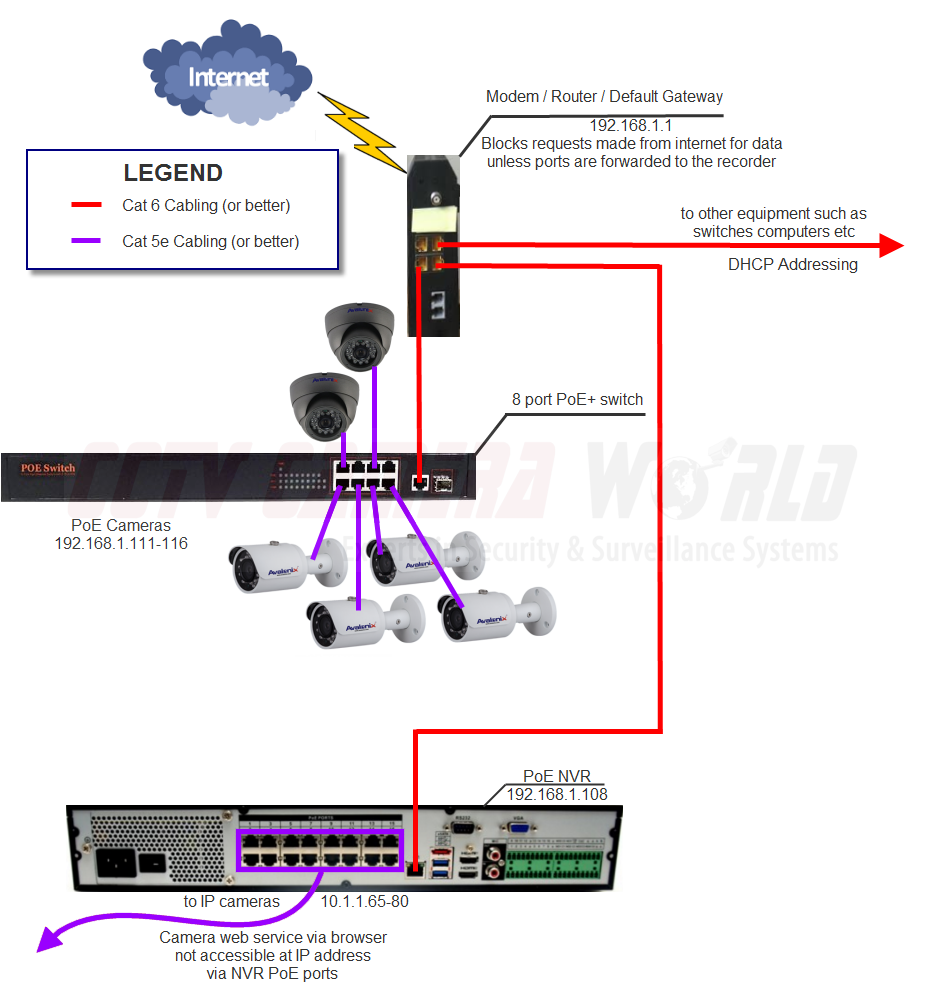
Figure 2-3 PoE NVR
[+] Click Image to enlarge
This is why it is ideal to have a routing device that can handle the bandwidth on a full load. It's also important to understand the limitations of ADSL and other slow internet services like cable. While your internet speeds have no bearing on viewing your cameras over the LAN, the upload speeds do come into play when attempting to view the cameras remotely. The DVR or NVR must send the data to you through the internet. Let's say you have a 16 camera surveillance system with 16x 4MP cameras. With the bandwidth limitations imposed by cable and DSL internet providers, you'll never be able to view all sixteen 4mp cameras in full quality. In fact, with DSL you'll be lucky to view one camera in low quality. If you want to view a 4K camera in full detail, Verizon FiOS or Google Fiber will be required at that location or another comparable fiber optic service that offers good upload speeds.
Our systems do provide a second substream that is of lower quality that you can use just to monitor a few cameras at a time using a slow cable modem 5Mbps upload speed connection. You can manage the resolution and bit rate of the second stream to suit your needs on your network. Don't expect a great image though. Your high-quality main-stream is still being recorded at its set resolution for you to be able to go back and review or export video in full quality. Not everyone is willing to move to a location with fiber optic internet service and pay for a good package, so there needs to be a way to get them the functionality of viewing. The Sub-Stream is the answer.
Additional Networking Support
Our goal is to provide you with enough information to be able to finish the install on your own. If you'd like hands-on assistance configuring your network, including port forwarding, you may make an inquiry using the Submit a Support Question form to create a ticket. We do charge to configure your network.