

How to Connect an Analog PTZ Camera Using Video Power Data Baluns and Ethernet Cable

Installing an analog Pan Tilt Zoom Camera (PTZ Camera) has a little more complexity to it than a regular camera alone. There are 2 RS485 leads that also need to be wired to the DVR or PTZ Controller. Using Video/Power/Data Cable can be costly. However there is an alternative. If you use a pair of Video Power Data PTZ Baluns you can wire the camera to your DVR using a cost effective CAT 6 network cable.
Today we're going to show you how to connect your baluns for Video/Power/Data to your PTZ Camera. One note before we get started, this method will only work with runs 100ft or less for cameras with power requirements for 24VAC 3A, but longer for cameras with lower wattage requirements. The limiting factor is voltage drop for camera power over the network cable. Depending on the quality of the cable you use, whether it is full solid copper or CCA (copper clad aluminum) your results will vary. For long runs over 75ft, we recommend full solid copper wire since it is a better conductor, and CAT6 wire because it is 23 awg cable vs CAT5e which is 24 awg cable.
Getting Started
Before getting started make sure that you have all of the equipment you need for the project.
What you'll need:
- Analog PTZ Camera which can be found here
- Video Power RS485 Data Balun pair
- Male DC Power Terminal
- Female DC Power Terminal
- Cat 6 Ethernet cable 100ft or less
- Electrical Tape
- Precision Screwdrivers
- Security DVR Recorder
- PTZ Controller (Optional)
Now that you have everything needed gathered into one work-space let's get started.
Assembling the Components
In order for the PTZ Camera to function properly you need to make sure to assemble everything accurately.
Connecting a Balun to the PTZ Pigtail
You should have two identical baluns in front of you. Each of them containing:
- Male DC Jack
- Female DC Jack
- RS485 Leads
- BNC Video Connector
- Ethernet Port
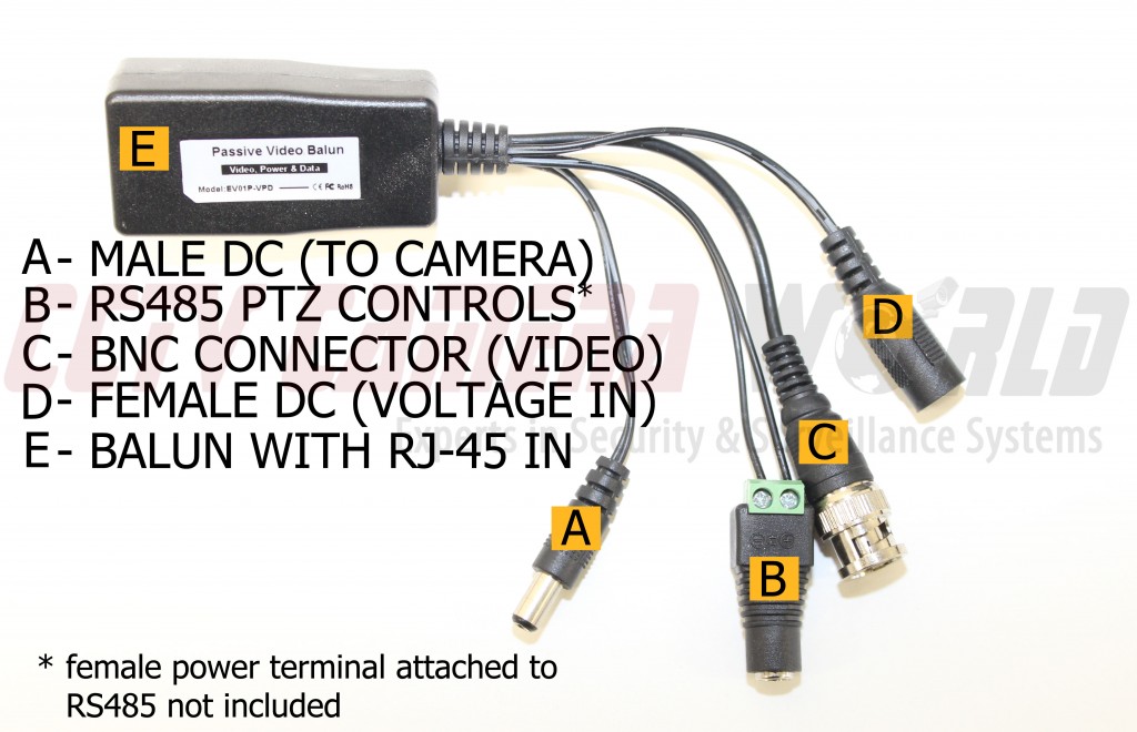
Here we've attached a Female DC Power Terminal [B] to one of the video balun's RS485 leads. This is the balun that will be used on the camera side. We attached the striped lead to the positive (+) pin and the solid black lead to the negative (-) pin. The leads should be made bare enough to form a good electrical connection, but not so much that they have a possibility of crosstalk. The leads should be screwed down firmly, and not have bare wire protruding from the end. It's not necessary to attach the terminal, but it does make assembly and disassembly easier at later times.
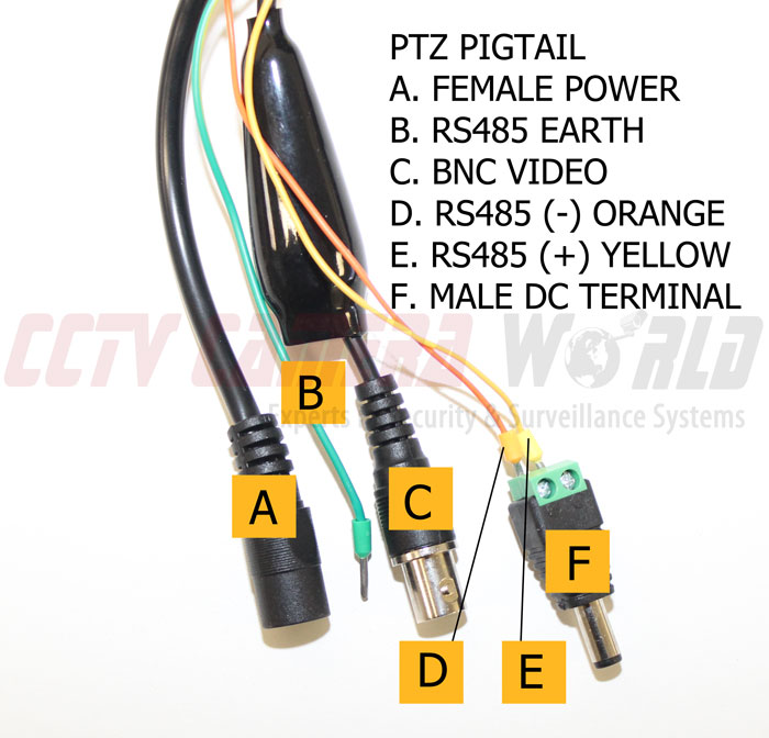
Here we attached the positive and negative RS485 leads from the camera to a Male DC Power Terminal. We have not connected the green wire to anything as it is specified as Earth. Once again make sure your connections are tight on the terminal and will not touch or create crosstalk.
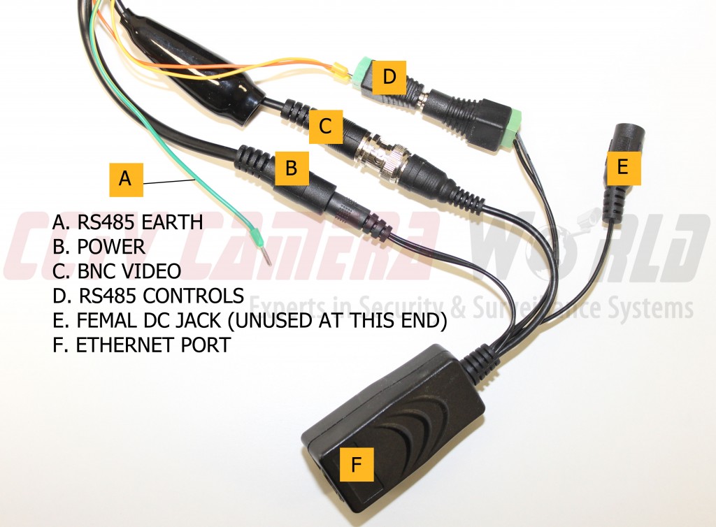
Here we have connected the balun to the camera's pigtail. The female DC jack [E] is unused on this end. It doesn't matter which balun you use as long as the connections you see are the same.
Connecting the Video Balun RS485 Leads to a PTZ Controller
This step will vary depending on your setup. One will be if you have a physical PTZ Joystick Controller, the other will be for connecting the RS485 without a controller. If you do not have a PTZ Controller skip to the next step.
If you're using a PTZ Controller you might want to use an extra two lead wire to connect the RS485 leads. Doing so will give you some wiggle room on moving the controller around. For demonstration purposes we do not use one.
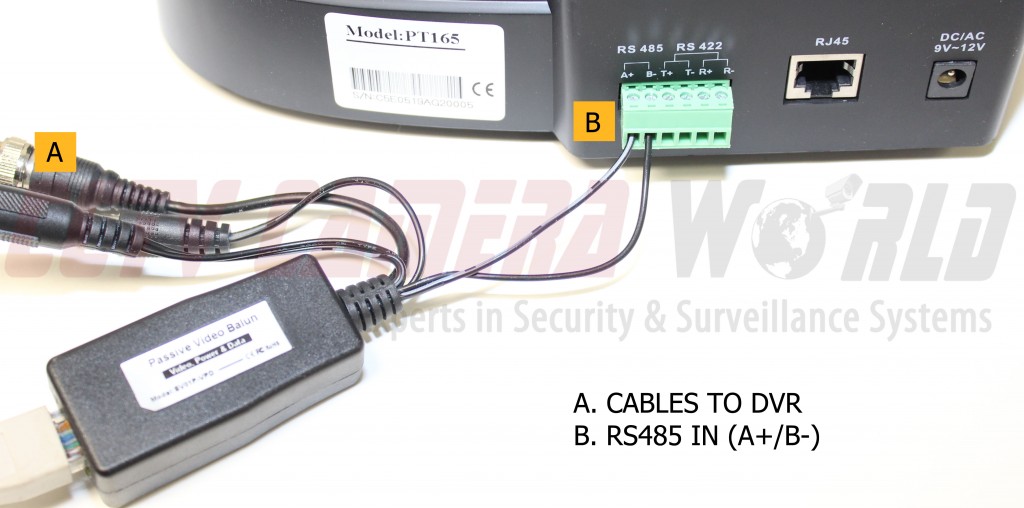
Here we have connected the RS485 leads from the balun to the controller. As you can see in [B], the striped lead is running to the positive port (A+) and the solid lead is running to the negative port (B-). They are tightened using the flat head screws on the top of the block.
Skip the next step, as your RS485 leads are now connected.
Connecting the Video Balun RS485 Leads to a DVR
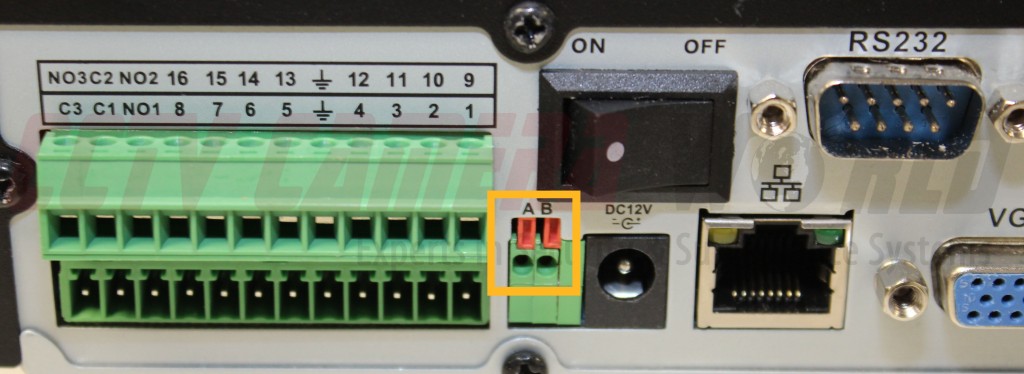
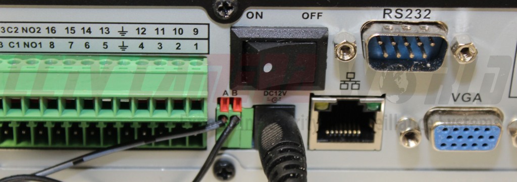
Connecting the RS485 leads to a DVR is fairly simple. The objects you see above the openings and below the "A" and "B" apply force to keep the wire connected in the port. Using a precision flat head screwdriver you can physically press them to allow you to feed the wire. Once the wire is in you can release the tab, and follow the same procedure for the second wire. Remember that A is positive (+) and B is negative (-). Therefore, A will receive the black/white striped line, and B will receive the solid black line.
You may want to use a two lead wire to extend the distance to your DVR from the balun so the BNC will reach your channel ports.
Connecting Video and Power
After your RS485 leads are installed you'll be moving on to video and power.

Here part [B] is already attached to your DVR or PTZ Controller. Now you'll connect part [C] to a channel input on your DVR and part [D] to your power source. Part [A] will be unused. For good practice cover this end with electrical tape.
Connecting the Video Baluns
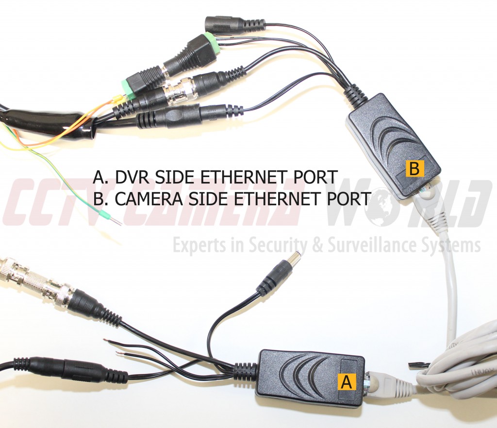
This is probably the easiest step. Connect your CAT5e or CAT6 network cable the RJ45 port on part [A]. Then connect the other end of the cable to the RJ45 port on part [B].
Final Step - DVR and Controller Configuration
Now that your cabling and connectors are correctly installed, you might notice that your controller does not control the camera. If that's the case there are a few configuration steps you need to take in order to pair the controller with your PTZ Camera. You'll have to make sure you match the Baudrate and ID to the PTZ Camera. This information is displayed on the camera's OSD display when it boots up. Here is what our camera displays:
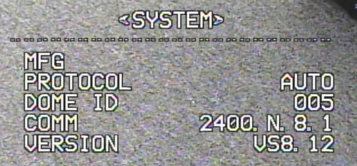
We are looking for 3 specific parameters:
- Dome ID or Address - in this case it is 005
- Baud Rate - The COMM line is the same as baud rate. It can be one of the following values: 1200, 2400, 4800, or 9600 bps. In our case it is 2400
- Protocol - Our camera says AUTO. This is the same as PelcoD for our PTZ cameras.
We have to enter these parameters in our DVR and PTZ controller to establish communication to the camera so we can command it to move.
DVR Controls
Select your PTZ Camera on the DVR and view it full screen. Once it's on full screen follow these steps:
- right-click the screen
- select main menu
- choose system in the bottom right
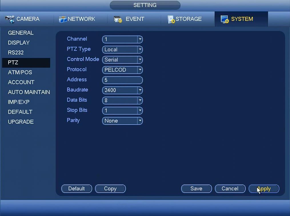
- choose PTZ on the left an you will see the SETTING screen above.
Now enter the settings for your camera by following the changes below:
- Channel: select Channel or Camera Number on DVR that you camera is connected to on the back of the DVR
- PTZ Type = Local
- Control Mode = Serial
- Protocol = PELCOD
- Address = 5 (identified on the camera's OSD)
- Baudrate = 2400 (identified on the camera's OSD)
- Data Bits = 8 (always going to be this value)
- Stop Bits = 1 (always going to be this value)
- Parity = None (always going to be this value)
After the above is configured, go to the monitor screen and:
- Right-click anywhere on the full screen view
- Select PTZ
- Use the controls to Pan Tilt or Zoom
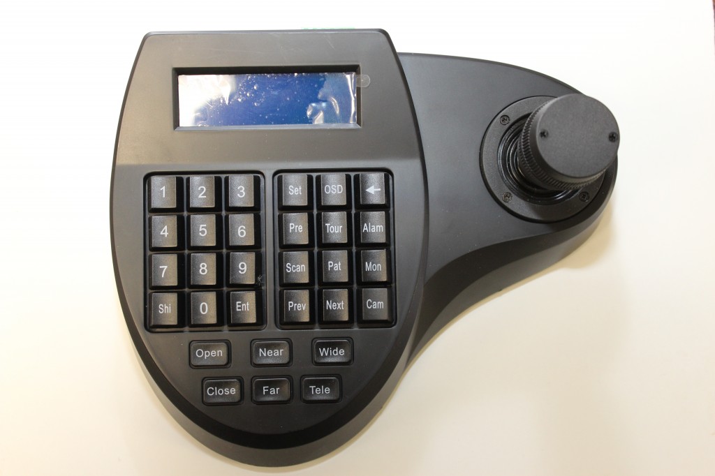
PTZ Controller
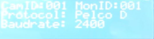
Here you will match the Baudrate and Camera ID. Both are displayed on the camera's OSD. Once they match you'll be controlling your PTZ Camera with a PTZ Joystick Controller. If you are using our PT165 PTZ Controller, first enter the camera number in 3 digit form. So for camera number 5, enter 005 and then press the CAM button. If you've already set the controller to the appropriate Baud Rate and Protocol, then once you enter the correct camera ID you will have control of your PTZ camera.