

Security Camera System setup with Fiber Optic Cable

A common challenge when installing a security system is the transmission distance limitation of Ethernet cabling. IP cameras that are part of a modern surveillance system are deployed using PoE technology that involves the use of copper based network cabling like CAT5e or CAT6 that has a data transmission limit of 100m (328ft). While that is adequate for installations for a home or small business, large scale installations may need to use a couple of different connection methods.

The most common method of extending beyond the 100m limit for each PoE camera is a PoE Extender. The usual solution involves using a PoE switch with at least 30W power output, and a PoE Extender every 100m to re-energize the data signal. If you have several cameras, the cost of long range PoE setups can be costly when you account for the cost of the extenders, and difficult to accomplish for locations where it is difficult to enclose an extender in the middle of the line.
For some IP camera setups it may be easier to deploy the cameras in sectors where they are supplied PoE connections from a PoE switch that is within the 100m distance, and then connect the PoE switch back to a switch or router closer to the NVR. A switch can be linked back to another switch or router up to 100m away over CAT5e or CAT6, but if your cabling runs are longer, then a more modern cabling option is needed.
Thanks to advances in cabling technology, fiber optic equipment and cabling is becoming more affordable and within reach for the everyday user. A fiber optic solution is far simpler, economical, and allows for greater distances between switches when designing and deploying a network to install IP cameras. You can combine PoE switches with available fiber optic uplink connections together to form a heterogeneous system that takes advantage of both copper based cable for PoE, and fiber optic cable for long distance transmission between switches in the network.
Complex installations involving interconnects over 100m or 328ft bring us to the point of comparing Fiber Optic Cable vs Copper Cable such as CAT5E.
Fiber Optic Cable vs Copper Network Cabling
| Fiber Optic | Copper | |
|---|---|---|
| Lifespan | 30-50 Years | 5 Years |
| Max Distance | 12 miles | 328 feet |
| Weight per 1000ft | 4 lbs | 39 lbs |
| Maximum Bandwidth (depends on equipment) |
69Tbps | 10Gbps |
| Security | Difficult to Tap | Easy to Tap |
| Noise | Immune | Susceptible to EMI |
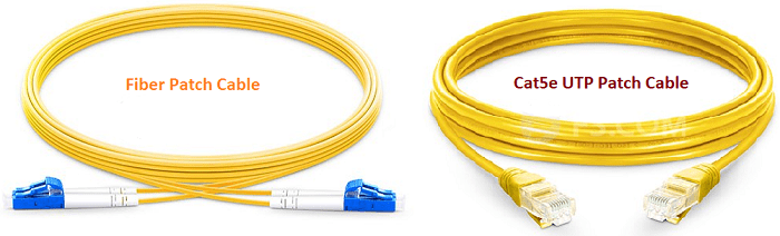
What is Fiber Optic Cable?
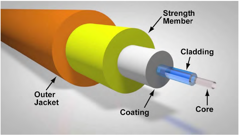
Fiber optic cables are made up of tiny strands of glass that use light, rather than electricity, to send and receive computer data. Strands in fiber optic cabling are extremely thin, sometimes thinner than human hair. The strands of glass fiber, called the core, are insulated inside of a layer of material known as cladding. Finally the cladding is wrapped in another material known as a buffer or coating, and then wrapped again in a cable jacket or insulator, which completes the fiber optic cable.
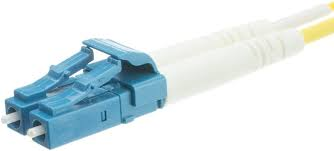
Due to the way that fiber optic communication works, fiber optic cables used to link switches are usually composed of two separate wires that are attached to one another and terminate into a connector.
How far can fiber optic connections transmit?
Fiber optic connections are great for long distance network transmission but you may be wondering if there is a limit and what that limit might be. It’s hard to give a definite answer because the limit is determined by the equipment that is used. As a baseline, the limit will always exceed the 328ft or 100m limit that copper cabling such as CAT5e or CAT6 offers.
Generally speaking the specifications of the PoE switch, SFP module, and cable will determine the unique limit to each group of hardware. Be sure to check the owner’s manual, specification sheet, or features list of your equipment to learn what the limits are. If that information is not readily available contact the manufacturer or vendor you purchased your fiber optic equipment from. The limit will be determined by the "shortest" link in the chain, which is usually the SFP module that determines signal transmission distance.
Who should use fiber optical cable?
Fiber optic cable is useful for anyone who is seeking to exceed the limitation of copper-based Ethernet network cabling. Fiber optic cabling and equipment is no longer too expensive to consider when planning a local network for security cameras or a wide area computer network. An added benefit of using fiber optic cabling is more available bandwidth and better throughput for connection speeds.
What equipment is required?
To successfully setup an IP security camera system over a network using fiber optic cable you will need the following equipment:
- Security camera recorder* - NVR is needed if you are deploying a system of PoE cameras only
- PoE cameras
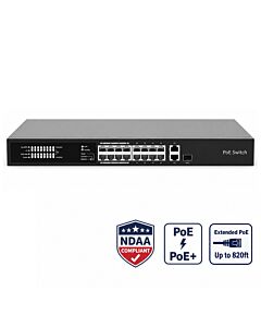
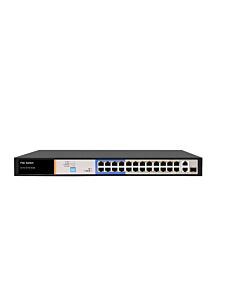
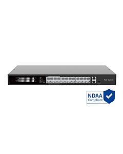
- 2 or more 802.3af/at compliant PoE Switches with 2 Fiber Optic SFP Uplink Ports on each switch
- Fiber optic SFP modules - 1 for each SFP Uplink port you intend to use
- Fiber optic cable within limits of the SFP
- Ethernet networking cable to connect PoE cameras to PoE Switches
- A router or modem**
* You can also use a coax DVR/XVR if you already have coax security cameras, and are interested in setting up a hybrid camera system. For more information consider reading our How to add IP cameras to a Security DVR article.
** A router or modem is only necessary if you want to view the security cameras remotely. All of our PoE systems can be used without an internet connection
How to use Fiber Optic Cable in a security camera system?
IP security systems require a computer network composed of PoE switches to send power and data to the cameras and for the cameras to talk to the network video recorder. Fiber optic cable is used in a security camera system to link PoE switches together to the NVR when cabling lengths longer than 328ft are required.
In the following walk-through video tutorial we explain how to use fiber optic cable to create a network using fiber-enabled PoE switches. For more in depth information about the specifics of IP addressing and system design involved in deploying an IP security camera system over a network, be sure to refer to our full guide on how to deploy an IP camera system over the network.
You can simply use two of our PoE switch with fiber uplink ports to connect two buildings together.

Simple Setup of IP Camera System over Fiber
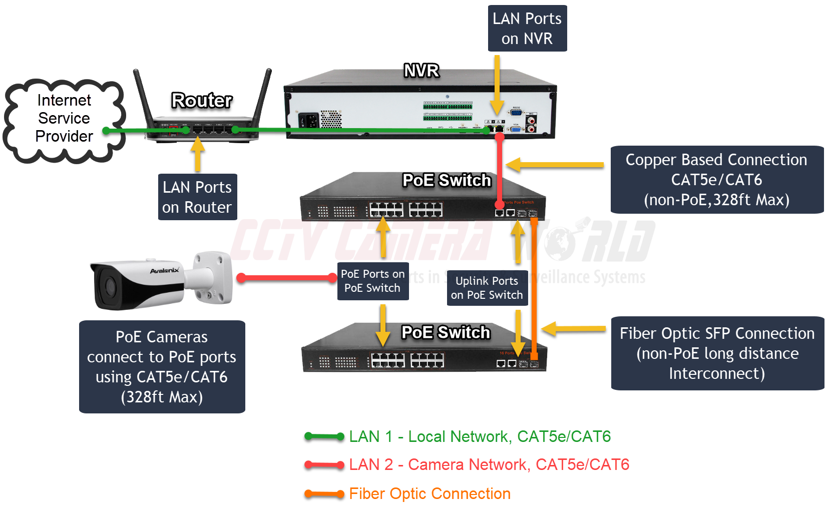
The image above shows a connection diagram for a simple connection between two switches. Such a setup for long range transmission is easy to deploy for someone with basic knowledge of IP addressing on computer networks. The only configuration that is required is IP addressing on the cameras and NVR.
If you have a managed switch, that may need an IP address of its own on the LAN. We do not recommend using complicated VLAN setups, and we do not support them either as it causes connectivity problems between the cameras and NVR.
Our recommended setup design simplifies system deployment by using an NVR with two LAN ports on the back. LAN1 connects to the router to provide internet connectivity to the NVR. LAN2 connects to the first PoE switch to create a “camera network” dedicated to the cameras and PoE switches. In this manner the cameras are isolated on their own simple network that ties back to the NVR.
Below is an overview of the steps necessary to setup the IP camera system pictured above:
- Planning and installing cable runs for switches and cameras is the first thing you should do when installing any type of security camera system.
- Install a fiber cable (orange line) to interconnect the two PoE switches over a long distance run.
- Install an Ethernet cable (red lines) for each IP camera you intend to install.
- Make sure there are Ethernet cables to connect the router, NVR and primary switch as well.
- After installing the cables you would begin connecting devices:
- Connect one end of the fiber optic cable into an SFP module and into the first PoE switch. Do the same for the secondary switch. Check the indicator lights for the SFP port on each switch to confirm there is a connection.
- Connect the First PoE switch to the NVR using the Ethernet uplink port on the switch.
- Connect the Ethernet cables for cameras to the PoE ports on each switch. If the cameras are installed with properly crimped cables they will power on and connect to the network.
Note: be sure to use the Ethernet uplink port that does not share the same port number as the SFP uplink port that is in use. For example, if the SFP port is numbered 17 on the switch, use Ethernet uplink port 18 to connect the Ethernet cable from the switch to the NVR.
- You have now successfully deployed a fiber optic network to host security cameras. The next steps, as fully described in our IP camera system over the network guide, include:
- Configuring an IP address for the NVR on the network
- Initializing and setting unique IP addresses for the IP Cameras
- Adding the IP cameras to the NVR
- Setting up the PC software or remote viewing app
Complex Setup of IP Camera System over Fiber
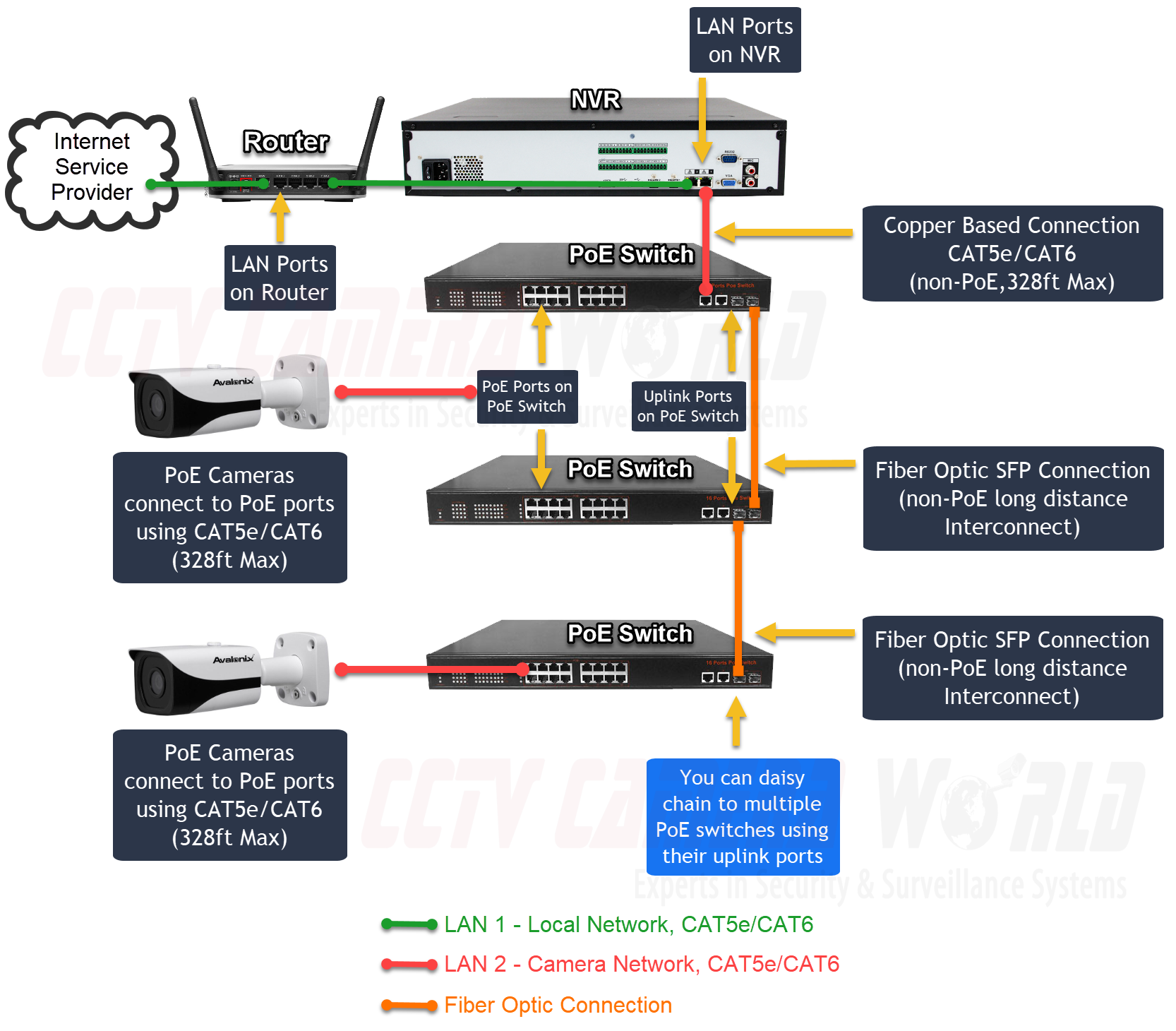
The system diagram pictured above is similar to the one in the Simple Setup, except for the addition of a third PoE switch. If you have another area that requires another PoE switch farther away you can easily daisy chain PoE switches using the SFP fiber optic port or the Ethernet port. Other than connecting additional PoE switches the rest of the installation and setup process is the same as a simple two switch setup.
Sources
https://engineer-educators.com/topic/basic-structure-of-an-optical-fiber/